
Powertrain sizing failures are among the most expensive engineering setbacks in industrial UAV development. Once carbon-fiber arm molds are machined, motor mount geometries are frozen, and power distribution harnesses are potted, discovering that an aircraft overheats in hover or misses endurance targets by 20% forces months of redesign and tool re-spins.
The root cause of most sizing errors is deceptively simple: engineering teams frequently size propulsion systems around catalog peak thrust ratings and isolated maximum g/W figures, rather than anchoring their design to the actual hover operating point under dynamic electrical and thermal conditions.
This engineering white paper presents the standardized Five-Step Powertrain Sizing Chain used by IPET SYSTEM application engineers, complete with dynamometer bench data, a fully worked 10.4 kg quadcopter sizing calculation with the IPET I7, and a pre-tooling verification checklist.
- Operating Point Primacy: Size propulsion systems for sustained efficiency at per-rotor hover thrust (Thover = MTOW / N), not peak catalog thrust or light-load maximum g/W.
- Five-Step Architecture: Follow the strict closed-loop flow: Freeze true operational MTOW → Calculate per-rotor hover load → Establish 1.8:1–2.2:1 TWR → Select matched motor/ESC/propeller stack → Close thermal and electrical discharge budgets.
- I-Series Rated Hover Anchors: Base sizing on verified continuous bench points: I7 delivers 12.82 g/W @ 2.68 kg/rotor (10–14 kg quads); I8 delivers 12.1 g/W @ 4.0 kg/rotor (16–18 kg quads).
- Bus & Avionics Isolation: Standardize on 12–14S architectures (max 61V); ensure avionics and telemetry receive isolated power, as industrial FOC ESCs contain no built-in BEC.
1. Why Catalog Peaks Mislead OEM Sizing
Component datasheets typically highlight two headline metrics: Maximum Thrust (e.g., 7.5 kgf) and Peak Efficiency (e.g., 14.5 g/W). Designing an industrial multirotor around either figure leads to predictable in-flight failures due to three physical mechanisms:
| Catalog Metric | Datasheet Assumption | Operational Reality in Flight |
|---|---|---|
| Maximum Thrust | Motor pushes peak power at 100% throttle on a test bench for 5–10 seconds. | Flight hover occurs at 40%–48% throttle. Sizing motors for extreme peak thrust forces hover into low magnetic utilization and high base stator weight. |
| Peak g/W Efficiency | Measured at 15%–25% throttle with minimal aerodynamic disk loading (e.g., 800 g thrust on a 30″ prop). | A 12 kg industrial quad requires 3.0 kg thrust per rotor. At this operating point, induced drag and copper losses reduce efficiency far below peak catalog numbers. |
| Continuous Current | Rated with direct 15 m/s ducted fan cooling in an open room at 20°C ambient. | Motors operate in stagnant boundary layers behind camera gimbals or in 40°C summer ambient, triggering steady-state coil overheating. |
When selecting a propulsion stack, the only efficiency metric that governs mission flight time is the system g/W delivered at the exact sustained hover thrust under nominal bus voltage.
2. The Five-Step Powertrain Sizing Chain
To eliminate sizing guesswork, IPET SYSTEM engineers apply a closed-loop five-step sizing chain before locking carbon-fiber chassis geometry or procurement specifications.
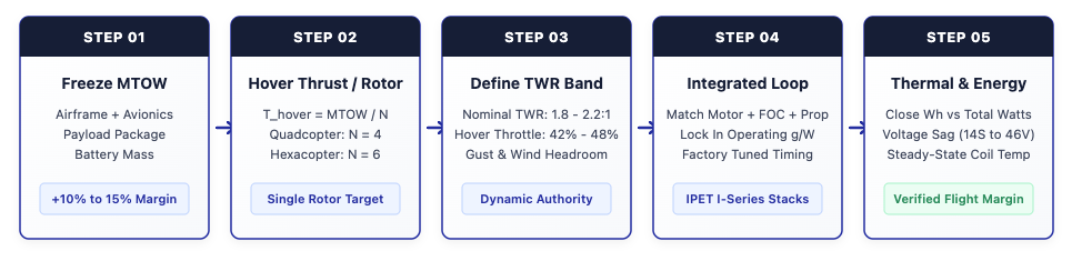
Step 1: Freeze True Operational MTOW
Never size propulsion from bare-frame dry weight. True Maximum Takeoff Weight (MTOW) must account for all sub-allocations plus an engineering growth buffer:
Step 2: Calculate Required Per-Rotor Hover Thrust
Divide target MTOW by the number of active lifting rotors (N). For a quadcopter, N = 4; for a hexacopter, N = 6:
Step 3: Define Dynamic TWR and Throttle Headroom
An industrial multirotor requires adequate dynamic control authority to arrest rapid descents, execute coordinated turns, and reject high-altitude wind gusts. The recommended Thrust-to-Weight Ratio (TWR) targets are:
- Nominal Industrial TWR: 1.8:1 to 2.2:1 (Hover occurs at 42%–48% throttle on nominal bus).
- Minimum Safe TWR (Depleted Battery): 1.6:1 at 3.3V/cell cut-off.
- Over-Sized Warning (>2.8:1): Motor operates in low-efficiency light-load regimes; attitude control becomes twitchy with excessive ESC deadband.
Step 4: Integrated Loop Matching (Motor + FOC + Propeller)
Rather than mixing motors from one vendor, propellers from another, and generic drone ESCs, treat the powertrain as an integrated electromechanical loop. Stator pole count, coil inductance, FOC commutation frequency, and propeller chord distribution must be harmonized. IPET I-Series integrated powertrains are factory-tuned to eliminate phase lag and commutation desynchronization under rapid step-throttle inputs.
Step 5: Close Thermal and Energy Budgets Across Discharge Sag
Verify that the battery pack can deliver required hover watts across its full state-of-charge (SoC) envelope. As bus voltage sags from 58.8V down to 46.2V on 14S, motor phase current rises to maintain thrust, increasing resistive copper losses (I2R). Sizing is only valid if motor coil temperatures stabilize below 85°C in steady-state hover.
3. Worked Engineering Case Study: 10.4 kg Quad with IPET I7
To demonstrate the five-step method in practice, consider an OEM engineering requirement for an industrial inspection drone operating with a 1.2 kg stabilized sensor payload:
- Airframe: 1000 mm carbon-fiber quadcopter (N = 4).
- Total All-Up Weight (MTOW): 10,400 g (10.4 kg).
- Battery Package: 14S Solid-State / Semi-Solid pack, 30,000 mAh nominal capacity.
- Nominal Battery Energy: 14S × 3.7V × 30Ah = 1,554 Wh (Pack mass: 4,850 g).
- Usable Discharge (DoD 85%): 1,554 Wh × 0.85 = 1,320.9 Wh.
- Continuous Avionics Draw: 35 W (Companion computer, telemetry, gimbal avionics).
Applying the five-step sizing chain step-by-step:
This calculated performance closely matches empirical field flight test logs of the IPET I7 Quadcopter, which recorded 124 minutes of forward flight at 10.35 kg MTOW under clean aerodynamic conditions.
4. Reading the Dyno Benchmark Curve
The relationship between rotor thrust, motor phase current, and overall system efficiency is fundamentally nonlinear. Dynamometer sweeps of the IPET I7 integrated powertrain demonstrate how efficiency shifts across the flight envelope:

| Bus Voltage | Throttle | Thrust (gf) | Input Power | System g/W | Operating Context |
|---|---|---|---|---|---|
| ≈54 V | 40% | 2,210 gf | 165 W | 13.39 | Light-weight hover (sub-9 kg MTOW) |
| ≈54 V | 45% | 2,684 gf | 209 W | 12.82 | Rated Hover Design Point |
| ≈60 V | 45% | 3,292 gf | 284 W | 11.59 | Fresh battery / heavier 13 kg MTOW |
| ≈60 V | 50% | 3,988 gf | 376 W | 10.62 | High payload / strong wind rejection |
| ≈54 V | 100% | 7,520 gf | 1,120 W | 6.71 | Emergency escape & gust margin |
Notice what occurs if the aircraft MTOW creeps upward from 10.4 kg to 14.0 kg: per-rotor hover thrust shifts from 2.6 kg to 3.5 kg. System efficiency drops from 12.82 g/W down to 11.20 g/W—a 12.6% efficiency loss. Compounded with lifting 3.6 kg of extra mass, total hover power surges from 846 W to 1,285 W, reducing flight time by over 34%.
5. IPET I-Series Integrated Propulsion Selection Matrix
To assist UAV system architects in selecting the optimal powertrain tier without over-sizing or under-sizing, IPET SYSTEM publishes verified operating points across the full I-Series family:
| Model | Bus & FOC ESC | Propeller | Max Thrust | Rated Hover Point | Target MTOW Band | Stack Weight |
|---|---|---|---|---|---|---|
| I5 | 6–8S FOC 30A | 18″–24″ | 4.2 kg | 13.3 g/W @ 1.3 kg | 4–6 kg (Quad) 6–9 kg (Hexa) | 350 g |
| I7 | 12–14S FOC 50A (Max 61V) | I30 30″ Carbon | 7.5 kg | 12.82 g/W @ 2.68 kg | 10–14 kg (Quad) 15–21 kg (Hexa) | 528 ± 2% g |
| I8 | 12–14S FOC 50A (Max 61V) | I36-S 36″ Carbon | 11.0 kg | 12.10 g/W @ 4.0 kg | 16–18 kg (Quad) 24–27 kg (Hexa) | 715 g |
| I9 | 12–14S FOC 50A (Max 61V) | 36″ Folding Carbon | 15.0 kg | 12.70 g/W @ 4.5 kg | 20–24 kg (Quad) 30–36 kg (Hexa) | 994 g |
| I11 | 12–14S FOC 70A (Max 61V) | 42″ Folding Carbon | 26.5 kg | 10.00 g/W @ 10.0 kg | 40–48 kg (Quad) 60–72 kg (Hexa) | 1,385 g |
For detailed testing methodologies and validation criteria behind these dyno figures, read our guide to How to Evaluate UAV Endurance Test Data. For payload-to-energy trade studies, see Flight Time vs. Mission Efficiency in Industrial UAVs and Why Bigger Batteries Don’t Always Extend Flight Time.
6. Five Classic Sizing Failure Modes & Verification Checklist
Before releasing chassis CAD files for tooling, audit your propulsion design against these five common engineering pitfalls:
- Motor KV Oversizing: Selecting high KV to achieve fast maximum dash speeds pushes hover throttle down to 25%–30%, causing low propeller Reynolds efficiency and erratic altitude hold.
- Cold-Ambient Battery Sag: Sizing on room-temperature battery impedance without modeling cell internal resistance increase at 0°C or −10°C, which causes premature ESC low-voltage cut-off under hover load.
- FOC Commutation Timing Mismatch: Using generic multirotor ESCs on high-inductance, large-diameter pancake stators, leading to commutation slip during sudden wind shear recovery.
- Propeller-Fuselage Interference: Placing large-diameter propellers with less than 20% blade-tip-to-fuselage clearance, inducing aerodynamic blockage losses and high acoustic noise.
- Freezing Arm Geometry on Catalog Peaks: Cutting carbon tubes before testing the actual motor-propeller pair on a thrust dyno across the full 42V–61V voltage range.
Conclusion: Close the Loop Before Tooling
Industrial UAV performance is determined at the operating point, not the catalog peak. By decomposing true MTOW into per-rotor hover thrust, verifying efficiency on dyno curves, and adopting factory-integrated powertrain stacks, engineering teams can guarantee flight time targets on day one without costly airframe redesigns.
To evaluate your multirotor design or request the complete IPET Powertrain Sizing Calculation Sheet, contact the IPET SYSTEM Applications Engineering Team.
Engineering FAQ
Industrial multirotors spend 85% to 95% of their mission profile hovering or in low-speed cruise. Sizing for maximum catalog thrust forces normal flight into light-throttle magnetic saturation or oversized coil inertia, severely penalizing watt-hour efficiency.
IPET design guidance specifies a nominal hover throttle window of 42% to 48% at nominal battery voltage (approx. 54V on 14S). This reserves adequate dynamic headroom for wind gust rejection while keeping FOC switching losses minimal.
As a 14S pack discharges from 58.8V down to 46.2V, maintaining constant hover thrust requires higher phase current (I = P/V). Because resistive copper loss scales with I²R, system efficiency typically drops by 8% to 15% toward the end of flight.
No. IPET I-Series ESCs are industrial opto-isolated or DroneCAN systems without built-in BEC. Flight controllers, mission computers, and payloads must be powered from dedicated, isolated DC-DC power distribution modules.