
Executive Technical Overview
In commercial maritime UAV deployments, field maintenance records demonstrate that propulsion reliability issues frequently originate within structural airframe booms and internal wiring connections rather than inside motor windings alone. Moisture accumulation inside composite booms, galvanic oxidation of internal bullet connectors, and aerodynamic vibration fatigue present persistent failure vectors. This technical review evaluates the structural advantages of integrated, embedded ESC powertrains, highlighting how the IPET N-Series eliminates internal arm wiring failure points, improves structural mounting rigidity, and delivers an empirical 18.3°C reduction in ESC operating temperature.
1. Root-Cause Analysis: Field Failure Modes in Maritime Deployments
For original equipment manufacturers (OEMs) developing unmanned aircraft for offshore inspection, coastal defense, or maritime logistics, bridging the reliability gap between indoor bench testing and offshore deployment remains a critical engineering task. Multi-rotor platforms that operate without incident in dry terrestrial trials often experience elevated service calls when stationed in humid marine air.
Teardown analysis of affected multirotors reveals that electrical faults frequently occur within the airframe booms or at interconnecting wiring harnesses, rather than inside stator coils or central flight controllers.
The primary driver is structural layout. Traditional propulsion architectures separate the brushless motor, electronic speed controller (ESC), and motor bracket into distinct modules connected by long three-phase AC wiring routed through hollow carbon fiber booms. In coastal operating envelopes, this layout introduces distinct environmental and mechanical vulnerabilities.
2. Environmental Hazards of Arm-Routed Wiring in Coastal Service
Routing three high-current AC phase cables through a hollow composite boom exposes the propulsion system to three specific failure mechanisms in marine environments:
2.1 The Carbon Boom Condensation Trap
Carbon fiber composite tubes exhibit low transverse thermal conductivity compared to metals. During coastal flight operations in high ambient humidity (>85% RH), internal air temperature fluctuations cause moisture to condense against the cooler inner walls of the hollow boom. This condensation pools around internal bullet connectors and solder splices.
Over repeated operational cycles, saline condensation degrades connector plating, initiating galvanic oxidation. As contact resistance increases, local I2R resistive heating damages solder joints and introduces phase impedance imbalance, which can trigger sudden in-flight loss of motor synchronization (desync).
2.2 Radiated EMI from High-Frequency AC Phase Switching
In conventional configurations, each boom carries three unshielded phase conductors transmitting high-frequency PWM switching currents along the entire length of the arm. These long conductors radiate electromagnetic noise that can couple into nearby compass magnetometers, RTK GNSS receiver leads, and payload data lines.
2.3 Mechanical Chafing from Aerodynamic Boom Deflection
Turbulent coastal boundary layer winds subject industrial multirotors to continuous aerodynamic gusts. Cyclic bending and torsional deflection of the booms cause internal cables to vibrate against composite tube edges and entry grommets. Over prolonged flight hours, continuous fretting can wear through wire insulation jackets, creating ground-fault hazards.
3. The Integrated Solution: Short-Path Phase Coupling and Thermal Optimization
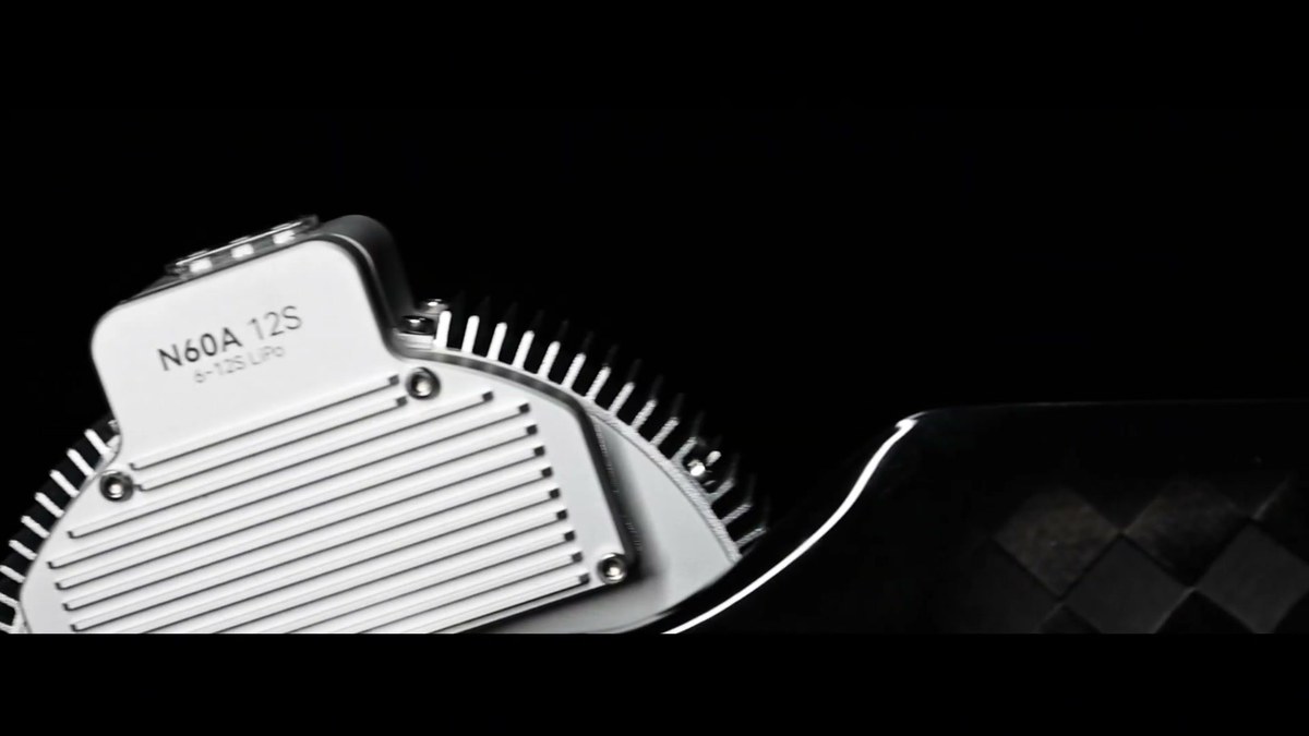
The IPET N-Series resolves these structural challenges by physically unifying the brushless motor, high-voltage FOC speed controller (N60A), and arm mounting clamp into a single sealed aluminum assembly:
- Direct Short-Path Phase Connection: Motor stator winding leads connect directly to the FOC drive inverter board inside the sealed CNC aluminum base without external phase harnesses. External AC phase cables, inline bullet connectors, and in-boom solder splices are eliminated completely.
- DC Power Rails and Shielded Digital Telemetry: Only stable DC bus lines and a shielded DroneCAN / PWM digital telemetry harness pass through the boom. Radiated electromagnetic emissions are substantially reduced, while the autopilot receives real-time digital telemetry including motor RPM, drive temperature, phase current, and bus voltage.
- Empirical Thermal Advantage: Enclosing conventional speed controllers inside hollow carbon tubes traps waste heat due to poor composite conductivity. In comparative infrared thermal testing under sustained 45-minute hover conditions (24.5°C ambient), an enclosed in-boom ESC reached a MOSFET temperature of 82.4°C. In contrast, the IPET integrated metal base—coupled directly into 15–20 m/s propeller downwash—stabilized at 64.1°C, an empirical reduction of ΔT = 18.3°C that eases thermal stress on capacitors and semiconductor switches.
4. Structural Rigidity and Vibration Suppression
Beyond electrical routing, powertrain mechanical mounting directly influences flight stability and airframe fatigue life:
- Monolithic 360-Degree CNC Clamping: The bottom of the motor housing is precision-machined as a monolithic CNC aluminum clamp tailored to the carbon boom. Uniform circumferential clamping distributes load around the composite tube, eliminating multi-piece bracket flexure and bolt loosening under gust loading.
- Sub-5 mg Dynamic Balancing: Out-of-factory dual-plane dynamic balancing is strictly controlled to <5 mg residual unbalance, suppressing rotational excitation frequencies that could otherwise couple into airframe resonance and flight controller IMU sensors.
5. OEM Assembly and Lifecycle Benefits
For drone manufacturers, adopting an integrated powertrain architecture provides tangible manufacturing and operational benefits:
| Design Metric | Modular Traditional Setup | IPET N-Series Integrated | OEM Operational Impact |
|---|---|---|---|
| Arm Wiring Architecture | 3 unshielded AC phase cables with bullet connectors inside boom | Direct DC power bus + shielded DroneCAN / PWM telemetry harness | Eliminates connector oxidation and in-boom phase short-circuit points. |
| ESC Drive Matching | Manual timing calibration; potential desync under step throttle loads | Factory-matched gate drive timings and stator inductance parameters | Ensures commutation stability across rapid dynamic throttle transitions. |
| Assembly Procedure | Manual wire cutting, stripping, soldering inline bullet connectors, separate ESC mounts | Single slide-on clamp mounting with pre-terminated harness | Substantially shortens propulsion assembly time and eliminates manual solder variation. |
| MOSFET Operating Temperature | Enclosed in boom: 82.4°C under 45-min hover (24.5°C ambient) | Downwash cooled: 64.1°C under same test (ΔT = 18.3°C reduction) | Significantly lowers thermal stress on drive electronics, extending component service life. |
Upgrade Your Industrial UAV Powertrain Architecture
Eliminate in-boom wiring failure points, simplify fleet assembly, and build all-weather commercial multirotors that withstand harsh maritime environments. Contact IPET SYSTEM engineering for integration drawings and test reports.
Explore N-Series Propulsion Systems →